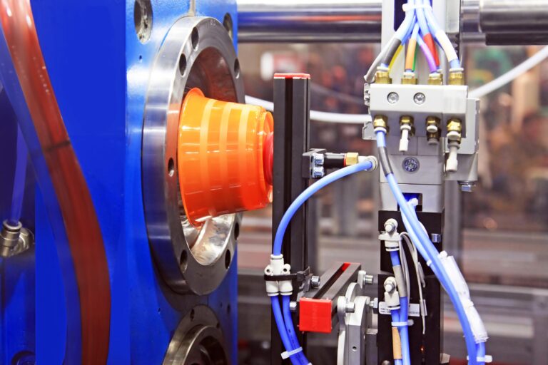
The majority of plastic products are made through injection molding due to its high production rates and low unit cost. Tolerances play a critical role, as incorrectly specified ones can lead to assembly issues, particularly given the substantial upfront cost of molds. This article delves into controlling injection molding tolerances for quality assurance, emphasizing design for manufacturing principles, material selection, tool design, and process control.
The Importance of Tolerancing
While the variations in manufacturing may be subtle, it’s crucial to establish an acceptable range of deviations from the nominal size to ensure proper functioning of the part. This becomes especially vital in assembling multiple parts.
For example, when connecting two flat parts with bolts, the locational tolerance of the holes on each part should cover the full range of possibilities. Even if one part is at its minimum tolerance and the other at its maximum, they still need to fit together during assembly. While this may seem straightforward, assembling multiple parts introduces the risk of one part causing the entire assembly to malfunction. Tolerance analyses, including the worst-case method, tolerance stack, and statistical analysis, prove valuable in optimizing injection-molding tolerances for assemblies with multiple parts.
Factors Influencing Tolerances
Part Design
To prevent issues like warping, excessive shrinking, and part misalignment, it’s crucial to employ Design for Manufacturing (DFM) principles during the part design phase. The best way to achieve this is by collaborating with an injection molding service early in the design process, preventing the need for costly redesigns later on.
Wall thickness: Varying wall thicknesses can result in uneven shrink rates in parts. When dealing with unavoidable thick areas, it’s essential to employ coring techniques to maintain uniform wall thickness. Uneven wall thickness can lead to part deformation, affecting tolerances and fit-up. Opting for thicker walls is not always the ideal solution for enhancing strength; instead, it’s preferable to use ribs and gussets wherever possible to bolster part strength.
Draft Angles: Draft angles play a critical role in ensuring smooth ejection from the tool. Suboptimal draft angles can lead to the part getting stuck during ejection, causing scraping and warping of the finished product. The recommended draft angles can vary between 0.5° to 3°, depending on the part design and surface finish.
Boss Features: Bosses are typically incorporated to facilitate fasteners in the assembly of multiple plastic parts. If bosses are overly thick, they can create sink marks on the part. Additionally, if not connected to side walls through ribs, bosses can undergo significant distortion, making the assembly of such parts nearly impossible.
Material Selection
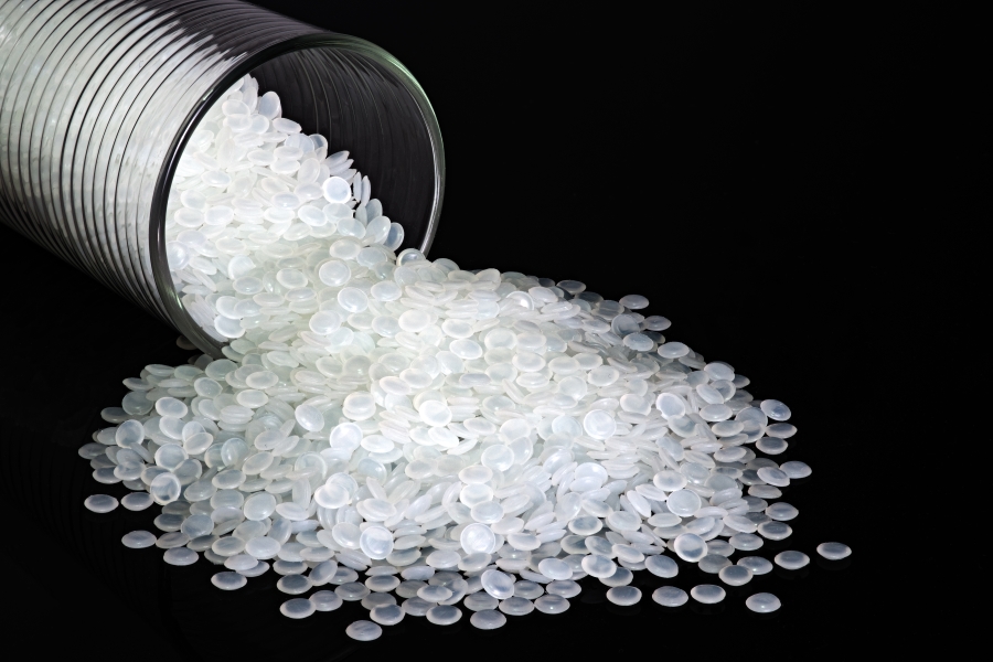
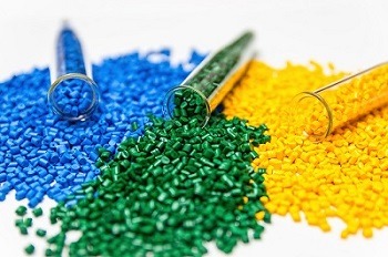
Manufacturing injection-molded plastics involves using a wide-range of resins, and the choice of materials is primarily guided by the specific application of the end product. Each resin has a different shrink rate.
When designing the molding tool, it’s crucial to consider this shrinkage. Typically, this is addressed by increasing the tool dimensions based on the material’s percentage shrinkage. In instances where multi-material assemblies are necessary, accommodating different shrinkage rates becomes a key factor. Neglecting to include suitable tolerances can lead to parts that don’t fit together, representing a costly mistake in the injection molding process.
Injection molding tolerances are primarily influenced by the material’s shrinkage and the geometry of the part. Before commencing the design and production of the tool, finalizing the material selection is a vital step. The design of the tool is closely tied to the chosen material(s).has.
Tool Design
After material selection, it’s common to oversized the tool to accommodate material shrinkage. However, shrinkage is not uniform across all dimensions; for instance, thicker parts cool differently than thinner ones. In complex parts with a mix of thin and thick walls, variable cooling rates can lead to warping or sink, significantly impacting injection molding tolerances and assembly fit-ups. To mitigate these effects, toolmakers consider the following factors when designing mold features:
Tool Cooling: Effective cooling control is crucial for maintaining consistent shrinkage rates. Inadequate cooling can result in uncontrolled shrinkage, causing parts to deviate significantly from tolerance requirements. Well-placed cooling channels enhance part consistency.
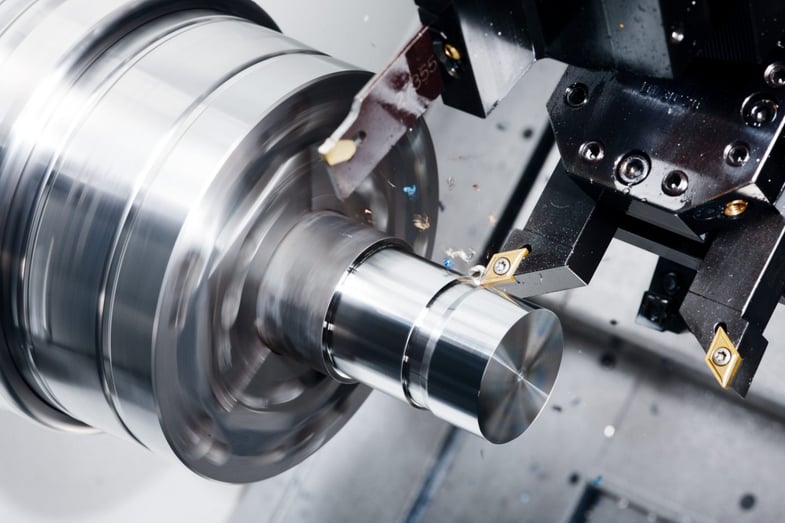
Tool Tolerances: Out-of-tolerance tooling adds inaccuracies to subsequent injection-molded parts, but such deviations are rare due to tight control and monitoring during CNC machining. Tools are often “steel-safe,” allowing critical dimensions or features to be adjusted through additional milling, facilitating fine-tuning based on finished part dimensions. For instance, a tightly toleranced hole feature may have a tool designed with the core pin at the wider side of the tolerance; if adjustment is needed, machining can make the hole thinner.
Ejector Pin Location: Swift ejection of molded parts is crucial to minimize cycle time. Suboptimal ejector pin positions can damage parts, particularly when materials exhibit flexibility leaving the tool, leading to warping and dimensional inconsistencies.
Gate Location: Proper gate placement is essential for cosmetic finishes. Incorrect positions can result in uneven fill rates, causing warping and erratic shrinkage. Complex parts often require multiple gates for even filling and to address these challenges.
Process Control
At RP Group, we provide an array of in-house prototyping and production services, encompassing plastic injection molding and CNC machining.
Our team of engineers is ready to assist you in selecting the most suitable plastic for your upcoming product. Additionally, we offer guidance on optimizing your designs for optimal results. Take the first step by uploading your CAD files today to receive a quote. Discover how we can support your requirements for rapid tooling, prototyping, and volume production.